Normally CATIA does not allow user to extrude an open or self intersecting profile. It is not possible to extrude such profile unless you define a thickness of the extrusion.
Follow these steps to extrude an open and/or self intersecting sketch.
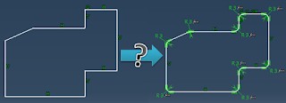
1. Create a sketch with an open and/or self intersecting profile - Fig.1.
 |
| Fig.1 |
2. Use this sketch to create a Pad, in the Feature Definition Error window click on Yes - Fig.2
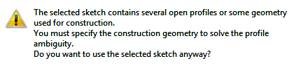 |
| Fig.2 |
3. In the Pad Definition, in Profile/Surface section check the option Thick - Fig.3. Click on More to expand the Pad Definition window.
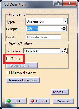 |
| Fig.3 |
4. Define thickness or thicknesses of the extrusion in the Thin Pad - Fig.4. And click on OK.
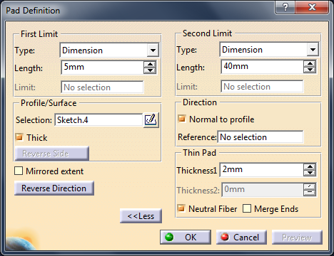 |
| Fig.4 |
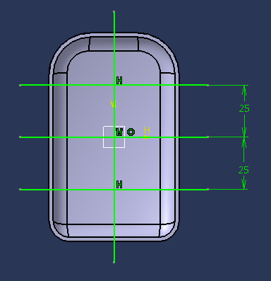
5. An extrusion of a self intersection and open profile has been created - Fig.5.
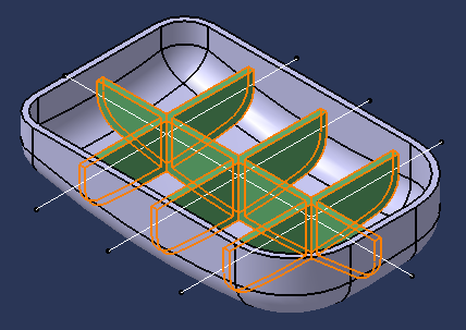 |
| Fig.5 |
Related posts:
How to make all these corners with only one command?