

The goal is to create an UDF to generate polygons. The inputs are point (center point), plane and a line (which controls orientation). The UDF allows user to change number of sides, radius of reference circle and to switch between inscribed and circumscribed polygon.
Follow these steps to create a Polygon UDF.
1. Create a new .CATPart, name it Polygon UDF, create two geometrical sets - Inputs and Polygon.
2. In Inputs geometrical set create isolated point, plane and line.
3. Create three parametres - Number of sides (type - Integer), Circle radius (type - Length), Switch (type - Integer). Drag and drop these parameters into Polygon GeoSet - Fig.1.
 |
| Fig.1 |
4. Add range to the Number of sides parameter. Click RMB on it, go to ...object > Definition, in new window Edit Parameter click RMB on the value box and select Add Range..., assign minimum value - 3, maximum value for the number of sides can be also assigned - Fig.2.
 |
| Fig.2 |
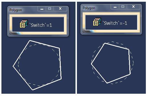
6. Add Multiple Values to the Switch parameter, multiple values are -1 and 1 - Fig.3. To add multiple values click RMB on the parameter, go to ...object > Definition, in new window Edit Parameter click RMB on the value box and select Add Multiple Values.
 |
| Fig.3 |
8. Use it as a center point to create a circle, use Plane 1 as a support, use the parameter Circle radius as a radius value - Fig.4. Name the circle REF CIRCLE.
 |
| Fig.4 |
 |
| Fig.5 |
11. Create a point on curve, name it INS PT 2. Curve is REF CIRCLE and Reference Point is INS PT 1, as a Distance to reference set Ratio of curve length, use following formula as Ratio (more details on Fig.6):
1/`Polygon\Number of sides`
 |
| Fig.6 |
13. Create a middle point on INS SIDE, name it MID PT.
14. Create a line on Plane.1 which is perpendicular to the INS SIDE, goes through MID PT and is infinite. Name it LINE NORMAL (Fig.7)
 |
| Fig.7 |
 |
| Fig.8 |
17. Use the ROTATION AXIS as a reference for the complete crown circular pattern. Object to Pattern is the INS SIDE line, number of the instances is the Number of sides parameter - Fig.9. Name it INS PATT.
 |
| Fig.9 |
18. Join the INS SIDE and INS PATT, name the join POL INS.
19. Use the POL INS to create a parallel curve. Plane.1 is the support, use the CIRCUM REF PT as a reference point, make sure that corners type is sharp (Fig.10). Name the feature POL CIRCUM.
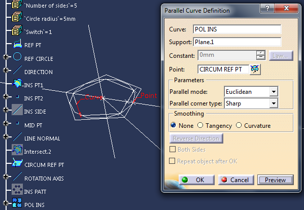 |
| Fig.10 |
`Polygon\Switch` * `Polygon\Circle radius`
21. Join POL INS and POL CIRCUM, make sure that the Check connexity option is turned off - Fig.11. Name it POL JOIN.
 |
| Fig.11 |
23. Drag and drop all the formulas to the Polygon GeoSet (Fig.12), hide all geometry except REF CIRCLE and POLYGON.
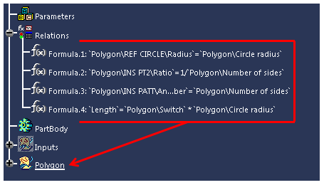 |
| Fig.12 |
 |
| Fig.13 |
26. In Userfeature Definition window (Fig.14) enter a name and select Polygon Geometrical Set. Polygon should appear in Selected components and all three inputs (not more) should appear in Inputs of components.
27. Go to the tab Parameters and publish the parameters (Number of sides, Circle radius, Switch). Optionally you can go to tab Properties to a chose new icon.
28. Go to Outputs tab and set POLYGON (Near Feature created in step #22) as a Main result and optionally REF CIRCLE as a second output - Fig.15. Click on OK.
29. Save the file and close it. The UDF can be used now.
Related posts:

 |
| Fig.14 |
28. Go to Outputs tab and set POLYGON (Near Feature created in step #22) as a Main result and optionally REF CIRCLE as a second output - Fig.15. Click on OK.
 |
| Fig.15 |
Related posts: